Login or create an account
CloseReturning Customer
I am a returning customer
Login or create an account
CloseRegister Account
If you already have an account with us, please login at the login form.
Your Account Has Been Created!
Thank you for registering with pcbzones!
You will be notified by e-mail once your account has been activated by the store owner.
If you have ANY questions about the operation of this online shop, please contact the store owner.
Account Logout
You have been logged off your account. It is now safe to leave the computer.
Your shopping cart has been saved, the items inside it will be restored whenever you log back into your account.
detail product
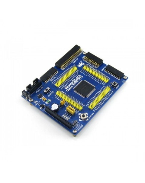
CPLD Development Board
- $28.14
- Ex Tax: $28.14
- Product Code: 5632
- Availability: In Stock
Overview
OpenEPM1270 is a CPLD development board that features the EPM1270 device onboard. It supports further expansion with various optional accessory boards for specific application. The modular and open design makes it the ideal for starting application development with ALTERA MAX II series CPLD devices.
What's On Board
- EPM1270:onboard CPLD device which features:
- Operating Frequency: 50MHz
- Operating Voltage: 1.5-3.3V
- Package: QFP144
- I/Os:116
- LEs: 1,270, the equivalent to 4,000 logic gates
- Debugging/Programming: JTAG
- AMS1117-3.3: 3.3V voltage regulator
- Power switch
- Power indicator
- LEDs: convenient for indicating I/O status and/or program running state
- Joystick: five positions
- Reset button
- Buzzer
- 8 I/Os interface: for connecting accessory boards
- 16 I/Os interface: for connecting accessory boards
- 8 I/Os interface: for connecting accessory boards
- 32 I/Os interface: for connecting accessory boards
For interface 9-12: it's possible to emulate the interfaces as ONE-WIRE, USART, I2C, SPI, PS/2, etc.
- 1-WIRE interface: for connecting 1-WIRE devices (TO-92 package), such as temperature sensor (DS18B20), electronic registration number (DS2401), etc.
- Character LCD interface: for connecting character LCD, such as the LCD1602 (5V Blue Backlight) in Package B
- 5V DC jack
- JTAG interface: for programming/debugging
- MCU pins connector: all the MCU pins are accessible on expansion connectors for further expansion
- LEDs jumper
- Buzzer jumper
For jumper 18-19:
- short the jumper to connect to I/Os used in example code
- open the jumper to connect to other custom pins via jumper wires
OpenEPM1270 Development Board
Connecting to LCD1602
Connecting to USB Blaster
Connecting to various peripherals
Connecting to USB UART Board via UART
Connecting to 8 SEG LED Board via 16I/Os
8 Push Buttons on the 8 I/Os interface
Connecting to 5 IO Keypad
4x4 Keypad on the 8 I/Os interface
Connecting to EEPROM Board via I2C
Connecting to VGA PS2 Board
Connecting to any accessory board you need
Note:
The OpenEPM1270 does NOT integrate any programming/debugging function, a programmer/debugger is required.
Accessory boards in the photo are NOT included in the OpenEPM1270 Standard Package.
Examples
OpenEPM1270 comes with various examples codes for the supported peripherals, which give you a quick start to develop your own application.
| Peripheral | Description | Interface | Verilog | VHDL |
|---|---|---|---|---|
| AT24CXX | EEPROM | I2C | Y | Y |
| FM24CXX | FRAM | I2C | Y | Y |
| DS18B20 | Temperature sensor | 1-WIRE | Y | Y |
| SP3232 | Serial communication | UART | Y | Y |
| SP3485 | Serial communication | UART | Y | Y |
| PL2303 | USB TO UART | UART | Y | Y |
| CY7C68013A | USB DEVICE | USB | Y | |
| Buzzer | Sound device | 1I/O(PWM) | Y | Y |
| PS/2 keyboard | Input device | PS/2 | Y | Y |
| Single buttons | Input device | ---- | Y | Y |
| 4x4 keypad | Input device | 8I/Os | Y | Y |
| Joystick | Input device | 5I/Os | Y | Y |
| LED | Display device | ---- | Y | Y |
| 8 SEG LED | Display device | 13I/Os | Y | Y |
| VGA monitor | Display device | VGA | Y | Y |
| Character LCD | Display device | 11I/Os | Y | Y |
Debugging/Programming Interfaces
The OpenEPM1270 integrates JTAG interface for programming/debugging.
JTAG Signal Names & Description
| Pin | Signal Name | Description |
|---|---|---|
| 1 | TCK | Clock signal |
| 2 | GND | Signal ground |
| 3 | TDO | Data from device |
| 4 | VCC(TRGT) | Target power supply |
| 5 | TMS | JTAG state machine control |
| 6 | NC | No connect |
| 7 | NC | No connect |
| 8 | NC | No connect |
| 9 | TDI | Data to device |
| 10 | GND | Signal ground |
JTAG Header Pinout
- Related Software (Quaters II etc.)
- Demo Code (Verilog and VHDL)
- Schematic (PDF)
- CPLD Development Documentations (Datasheets etc.)

